dimarts, 20 de desembre del 2011
dijous, 8 de desembre del 2011
Info sobre el track liner sensor sen0017

Aquí hi ha una mica d'informació (connexió dels cables)
Output connector: 3-wire interface (1 - signal, 2 - power is, 3 - power losses)
dijous, 10 de novembre del 2011
Manual del driver del motor
Aquest és el manual (inclou exemple de programació) del driver per al motor controlat per arduino.
http://www.dfrobot.com/wiki/index.php?title=Arduino_Motor_Shield_%28L293%29_%28SKU:_DRI0001%29
http://www.dfrobot.com/wiki/index.php?title=Arduino_Motor_Shield_%28L293%29_%28SKU:_DRI0001%29
dimarts, 8 de novembre del 2011
Outrun fuera de la pantalla
Bueno, posibilitats amb arduino+ imaginació i dedicació (trobat per l'Oriol Sánchez) http://dswii.es/41675/offtopic-outrun-fuera-de-la-pantalla-mas-bien-analogico/
dimarts, 18 d’octubre del 2011
dilluns, 17 d’octubre del 2011
OSHW Concurs: Arduino HardProgramming
Aquí hi ha els enunciats del concurs i la documentació del concurs
Open Source Hardware, electrònica i robòtica
Xerrades, tallers,... Aquí podeu veure videos i més... Alguns són molt interessants
Driver per al control de motors amb arduino
L'SN754410 substitueix a l'integrat L239D i pot controlar motors de 4,5V a 36V. Per un preu d'uns 2 euros
Algunes idees per projectes
Malgrat el nom, no té res de tutorial http://www.youtube.com/watch?NR=1&v=FRFf_d2pQJE
dimarts, 20 de setembre del 2011
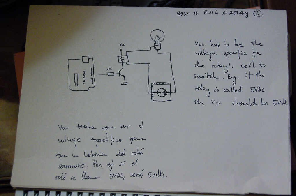
Conectar Arduino con una bombilla
Navegando y buscando por Internet, esa gran red de redes, he encontrado una manera de conectar una bombilla con lo que parece ser un relé. El circuito consta, del Arduino, 1K de resistencia y un relé conectado todo a la bombilla.
Sería una buena manera de empezar con electricidad para después hacer algo más grande. Compraré lo necesario y ya posteare el resultado.
Pongo dicha foto
diumenge, 18 de setembre del 2011
Jody Culkin: Còmic
Un còmic per introduir arduino i alguns projectes bàsics
http://www.jodyculkin.com/wp-content/uploads/2011/09/arduino-comic-latest3.pdf
http://www.jodyculkin.com/wp-content/uploads/2011/09/arduino-comic-latest3.pdf
Hack n mod: Top 40 Arduino Projects of the Web
Exemples de projectes. Els que he mirat venen amb instruccions, el programa i pressupost
dijous, 15 de setembre del 2011
Grupo Sabika: Exercicis de S4A
Aquí hi ha uns pocs però interessants exercicis per començar amb scratch i arduino.
divendres, 15 de juliol del 2011
dijous, 14 de juliol del 2011
Arduino Tutorial: Learn electronics with Arduino (Lady ADA)
Boníssima. Tutorial en anglès. A partir de la lliçó 3 és molt interessant, encara que només ho agafem com a propostes per fer amb scratch.


dimecres, 6 de juliol del 2011
dilluns, 4 de juliol del 2011
Getting Started\Processing.org
Doncs això. Com començar a programar amb processing: http://processing.org/learning/gettingstarted/
diumenge, 3 de juliol del 2011
LDR

Penso que podríem dissenyar un ratolí òptic que em anés movent a la pantalla en funció del moviment d'un llum extern. Seria el principi d'un seguidor del sol per a una placa solar.
dimecres, 29 de juny del 2011
Sensor NTC
Aquest és l'esquema de connexió de la resistència NTC a la placa arduino
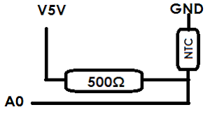
Els valors que he detectat són: a temperatura ambient (uns 25º) l'scratch em detecta un valor de 198
Prement fortament amb els dits (imagino que uns 38-39º) l'scratch em dona un valor de 175
Aquest és el datasheet del meu NTC http://www.cooking-hacks.com/skin/frontend/default/cooking/pdf/159-282-86001.pdf
Aplicacions: termòmetre, termòstat, control d'obertura de finestres o tancament de persianes en funció de la temperatura
dimarts, 31 de maig del 2011
Firmware per a controlar Arduino amb Scratch
Aquest firmware és necessari per a controlar l'Arduino des de l'Scratch. Heu de copiar el fitxer de text al programa Arduino i pujar-lo a la placa. El text és aquest:
//ARDUINO FIRMWARE FOR S4A SOFTWARE - http://seaside.citilab.eu/scratch/arduino

//INPUT/OUTPUT CONFIGURATION
  //digital outputs (digital pins 10,11 and 13)
  //analog outputs (digital pins 5, 6 and 9)
  //analog inputs (analog pins)
  //digital inputs (digital pins 2 and 3)
  //servomotors RC (digital pins 4, 7, 8 and 12)

char outputs[10];
int states[10];
int pulseWidth;
unsigned long initialPulseTime;
unsigned long lastDataReceivedTime;
//servomotor ISR variables
volatile int updateServoMotors = false;
volatile boolean newInterruption;

void setup()
{
  Serial.begin(38400);
  Serial.flush();
  configurePins();
  configureServomotors();
  lastDataReceivedTime = millis();
}

void loop()
{
  sendSensorValues();
  readSerialPort();
}

void configurePins()
{
  for (int index = 0; index < 10; index++)
  {
     states[index] = 0;
     pinMode(index+4, OUTPUT);
     digitalWrite(index+4, LOW); //reset pins
  }

  outputs[1] = 'a';//pin 5
  outputs[2] = 'a';//pin 6
  outputs[5] = 'a';//pin 9
  outputs[6] = 'd';//pin 10
  outputs[7] = 'd';//pin 11
  outputs[9] = 'd';//pin 13

  pinMode(2,INPUT);
  pinMode(3,INPUT);
  outputs[0] = 'c'; //pin 4
  outputs[3] = 'c'; //pin 7
  outputs[4] = 's'; //pin 8
  outputs[8] = 's'; //pin 12
}

void configureServomotors()
{//servomotors interruption configuration (interruption each 10 ms on timer2)
  newInterruption = false;
  updateServoMotors = false;
  TCCR2A = 0;
  TCCR2B = 1<<CS22 | 1<<CS21 | 1<<CS20;//preescaler = 1024
  TIMSK2 = (1<<TOIE2); //Timer2 Overflow Interrupt Enable
  TCNT2 = 100;   //start timer
}

void sendSensorValues()
{
     int sensorValues[6], readings[5], sensorIndex;

      for (sensorIndex = 0; sensorIndex < 6; sensorIndex++) //For analog sensors, calculate the median of 5 sensor readings in order to avoid variability and power surges
      {
        for (int p = 0; p < 5; p++)
          readings[p] = analogRead(sensorIndex);

        InsertionSort(readings, 5); //sort readings
        sensorValues[sensorIndex] = readings[2]; //select median reading
      }

     //send analog sensor values
     for (sensorIndex = 0; sensorIndex < 6; sensorIndex++)   ScratchBoardSensorReport(sensorIndex, sensorValues[sensorIndex]);

      //send digital sensor values
     ScratchBoardSensorReport(6, digitalRead(2)?1023:0);
     ScratchBoardSensorReport(7, digitalRead(3)?1023:0);
}

void InsertionSort(int* array, int n)
{
  for (int i = 1; i < n; i++)
    for (int j = i; (j > 0) && ( array[j] < array[j-1] ); j--)
      swap( array, j, j-1 );
}

void swap (int* array, int a, int b)
{
   int temp = array[a];
   array[a] = array[b];
   array[b] = temp;
}

void ScratchBoardSensorReport(int sensor, int value)
{ //PicoBoard protocol, 2 bytes per sensor
  Serial.print( B10000000
                 | ((sensor & B1111)<<3)
                 | ((value>>7) & B111),
                BYTE);
  Serial.print( value & B1111111, BYTE);
}

void readSerialPort()
{//read serial port until actuators plot has arrived

  int pin, inByte, sensorHighByte;
  boolean newSensorsPlot = false, complete = false;
  char parameter = '1';

   while (!complete)
   {
      if (updateServoMotors) updateServomotors();

      if (Serial.available())
      {
        inByte = Serial.read();
        lastDataReceivedTime = millis();

          if (parameter == '1')
          {
            if (inByte >= 128) //high byte (most significant bit equal to 1)
            {
              newSensorsPlot = true;
              sensorHighByte = inByte;
              pin = ((inByte >> 3) & 15);
            }
          }
          else if (parameter == '2')
          {
            states[pin - 4] = ((sensorHighByte & 7) << 7) + (inByte & 127);
            updateActuator(pin - 4);
            complete = (pin == 13);
          }

          if (newSensorsPlot)
          {
            if (parameter == '2') parameter = '1';
            else parameter++;
          }
      }
     else checkScratchDisconnection();
   }
}

void reset()
{//With xbee module, we need to simulate the setup execution that occurs when a usb connection is opened or closed without this module

  for (int pos = 0; pos < 10; pos++)  //stop all actuators
  {
     states[pos] = 0;
     digitalWrite(pos + 2, LOW);
  }

  //reset servomotors
  newInterruption = false;
  updateServoMotors = false;
  TCNT2 = 100;

  //protocol handshaking
  sendSensorValues();
  lastDataReceivedTime = millis();
}

void updateActuator(int pinNumber)
{
        if (outputs[pinNumber] == 'd')  digitalWrite(pinNumber + 4,states[pinNumber]);
        else if (outputs[pinNumber] == 'a')  analogWrite(pinNumber + 4, states[pinNumber]);
}

void updateServomotors()
{
   updateServoMotors = false;

    for (int p = 0; p < 10; p++)
    {
      if (outputs[p] == 'c') servomotorC(p + 4, states[p]);
      if (outputs[p] == 's') servomotorS(p + 4, states[p]);
    }
}

void servomotorC (int pinNumber, int dir)
{
    if (dir == 1) pulseWidth = 1300; //clockwise rotation
    else if (dir == 2) pulseWidth = 1700;////anticlockwise rotation
    else return;
    pulse(pinNumber);
}

void servomotorS (int pinNumber, int angle)
{
    if (angle < 0) pulseWidth = 0;
    else if (angle > 180) pulseWidth = 2400;
    else pulseWidth = (angle * 10) + 600;
    pulse(pinNumber);

}

void pulse (int pinNumber) {
    digitalWrite(pinNumber, HIGH);
    initialPulseTime = micros();
    while (micros() < pulseWidth + initialPulseTime){}
    digitalWrite(pinNumber, LOW);
}

void checkScratchDisconnection()
{//the reset is necessary when using an wireless arduino board (because we need to ensure that arduino isn't waiting the actuators state from Scratch) or when scratch isn't sending information (because is how serial port close is detected)
  if (millis() - lastDataReceivedTime > 1000)   reset(); //reset state if actuators reception timeout = one second
}

ISR(TIMER2_OVF_vect) //Timer1 overflow interrupt vector handler
{//Timer 2 => 8 bits counter => 256 clock ticks
 //preeescaler = 1024 => this routine is called 61 (16.000.000/256/1024) times per second approximately => interruption period =  1 / 16.000.000/256/1024 = 16,384 ms

 //as we need a 20 ms interruption period but timer2 doesn't have a suitable preescaler for this, we program the timer with a 10 ms interruption period and we consider an interruption every 2 times this routine is called.
 //to have a 10 ms interruption period, timer2 counter must overflow after 156 clock ticks => interruption period = 1 / 16.000.000/156/1024 = 9,984 ms => counter initial value (TCNT) = 100

  if (newInterruption)
  {
     TCNT2 = 100;  //reset timer
     updateServoMotors = true;
  }

  newInterruption = !newInterruption;
}
diumenge, 29 de maig del 2011
Jornada 2011 Scratch for Arduino
Conté instruccions per començar amb scratch i arduino. Cliqueu aqui per anar a la pagina de la Jornada.
divendres, 27 de maig del 2011
Curs d 209 d'Scratch
Aquí teniu l'enllaç al material del curs telemàtic d'Scratch: http://www.xtec.cat/formaciotic/dvdformacio/materials/td209/index.html
Arduino ja respon
Per fi arduino respon a les ordres de l'ordinador. Hem fet servir els exemples de l'aplicació Arduino: Basiks--> Blink i Fade. Amb scratch hi ha algun problema.
Subscriure's a:
Missatges (Atom)